SeSec
High end Digital Video Recorders with IRIG-B time-stamp,
GPS time-stamp or computer time stamp, Radar computer video monitor capture &
recording,
and advance rackmount servers and storage raid arrays. Please Scroll for
More views 
CONTACT:
E-mail: sales@cepoint.com
Tel1: (603)557-7464
Fax: 1(603)883-3266
Products Price rfq.htmList (download)
Rugged Portable Computer prices
RS-1702 QUAD-core Xeon 2U Carrier Grade Enterprise Servers
RS-1702 Quad core Telco Carrier Grade Linux or Windows Ent. servers AC or 28V DC p/s
RS-1702 QUAD Opteron 2U Carrier Grade Enterprise Servers
CONSULTING & INTEGRATION
SOLUTIONS:
Enterprise storage Overview
Rugged Field Portable computer w/12V-28V DC
Min-SAN /Storage Data Backup
IP STORAGE Raid Expansion
NAS (Network Attached Storage)
time stamping (scientific imaging)
CEP Cluster System Information
1U, 2U, 3U, Raid Servers, Workstations and Nodes
More Rack mount systems
4U, 5U Super servers
RF Microwave
Automotive color TV system
6.8" TFT LCD color display panel
Embedded Networking
Embedded Systems
Homeland security appliances
CCD Cameras Surveillance DVR
CCD Infrared Weather proof Surveillance camera
Frame Grabbers / Imaging System
Image and Motion Sensors
24-28 V DC POWER Supply
Shipboard computers and
28V DC or -48V DC powered 19" rackmount PC
Plasma Display & Airport video systems
Airborne Computers with 28V DC
Server Virtualization
Unified Storage


 Contact:
sales{AT}cepoint-DOT-com 603.883.7979. www.cepoint.com
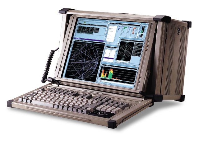
TRANSPAC-6300 HIGH RESOLUTION
Rugged Field Portable, Multifunctional Data Acquisition computer System for temperature, strain guage, accelerometer, transducer, and vibration testing measurements.Multiple PCI and PCI-express Expansion slots and DC-12, 24VDC or 28V DC power supply with Battery backup
TRANSPAC-6300 /DAS-6063T TransPAC is a
hardened, ruggedized portable with Optional 16-Channels Analog/Digital, multifunctional data
acquisition system, for testing , measurement, acquisition or data logging,
Easily expandable to 64 channels. Whether the
applications is Temperature transducer, strain, accelerometer or vibration
testing or measurements, DAS-6063T is built o handle the though demands. The
system hardware is comprised of up to optional 80 I/O plug-and-play PCI board, 3
ft. cable, and screw terminal/signal conditioning pod. Cold-junction
compensation is built-in to the DAS-6063T, which provides precise thermocouple
measurements, with channel-to-channel variation and

noise less than 0.2°C, and accuracy better than 1.0°C. A separate low-noise amplifier per TC channel allows for these exact measurements. TransPAC-6300 /DAS-6063T is available with OPTIONAL 7, 14 or 28 or 32 thermocouple input channels and an 8-channels RTD.
In addition to Analog and thermocouple inputs, DAS-6063T also provides 7 or 14 differential voltage input channels that offer 16-bit resolution and 13 programmable full-scale input ranges from ±156 mV to ±10V. per port .The 4 or 8 frequency input channels can
measure frequency or count pulses up to 10 MHz. Two timer output channels are capable of generating square
wave outputs up to 1 MHz. 24 or 48 digital I/O lines are also included, which can be programmed in 8-bit groups as
either inputs or outputs.
All inputs, including thermocouple inputs, voltage, frequency, and digital, can be synchronously scanned up to 200K readings/s, which provides accurate time correlation between all inputs. The 16-bit/100-kHz analog outputs can be used to generate waveforms with a virtually infinite waveform output length from the system memory.
All inputs and outputs are accessed via convenient screw terminals located on the signal conditioning pod. The cover
of the signal conditioning pod is easily removed to gain access to the screw terminals for signal connections.
Screw-terminal access to all voltage inputs, digital I/O, frequency I/O, and analog output
DAS-6063Tincludes a full suite of third party software including DaqView™ Out-of-the-Box™ software, plus drivers for DASYLab®, LabVIEW®,
TestPoint®, MATLAB, and Windows®-based
languages including Visual Basic®, and C++
mp Series Configurations*
Applications:
Production test
Vibration analysis
Stimulus/response analysis
Process monitoring and control
Temperature
Sound analysis
Automotive engine testing
FEATURES OVER VIEW (with optional Analog/Digital I/O card):
Rugged aluminum alloy hardened industrial chassis
Up to 16 or 32-Channel, 200 KS/s A/D easily
expandable to 64 or 128 channelsA/D 16-bit resolution
8- Digital I/O bits & 2 counter/timer
Built with powerful Intel Pentium 4 Dual-Core processor
1GB internal DDRAM memory
120GB internal storage shock mount hard disc drive
(
Removable or swappable storage option)3.5" floppy and 24 x CD-ROM
Rugged Flash Disk option
Expansion PCI, PCI-X or PCI-Express slots available
12- 15" TFT LCD display 1024 x768 with analog video converter
Display of multiple windows or reports
Up to 4 simultaneous window display view of tests or reports
Real-Time data acquisition or logging.
Data transfer or transport via removable media, TCP/IP or RS-232/422.
Reports or results in ASCII protocol, Excel spreadsheet
Built for Extreme harsh terrains and environments
Portable , Less 35lbs
Specifications & Ordering Information|
OPTION 1: TransPAC-6300 w/ 4-PCI slots, SSD & 24V DC or 110V AC ( Analog or Digital I/O not includd)OPTION 2 : The DAS-6063T provides 7,14, 28 or 32 differential channelsof TC/mV inputs (depending on factory configuration), and 8 RTD channels configured in 37-pin ports: P1, P2, P3. to physically connect the thermocouples or RTD’s via DBK screw box terminals that are signal conditioned. System Connector: All DBK options have a DB37 male,which mates with P1, P2, P3 on the Das-6063T system, or other DBK options TC/mV Connector DBK81: Board-mounted screw terminalsDBK82: Board-mounted screw terminalsDBK83: External pod-mounted screw terminalsDBK84: Mini-TC connectorsFunctions: TC types J, K, S, T, E, B, R, N; x100 (voltage)Inputs DBK81: 7 differential TC/mV inputsDBK82: 14 differential TC/mV inputsDBK83: 14 differential TC/mV inputsDBK84: 14 differential TC/mV inputsInput Voltage Range: ±100 mV**Input Impedance: 40M Ohm (differential); 20M Ohm(single-ended) Input Bandwidth: 4 HzInput Bias Current: 10 nA typCMRR: 100dB typMaximum Working Voltage (signal + common mode): ±10VOver-Voltage Protection: ±40VPower Requirements DBK81: 35 mA max from ±15V;2 mA max from +5V DBK82: 60 mA max from ±15V;2 mA max from +5V DBK83: 60 mA max from ±15V;2 mA max from +5V DBK84: 60 mA max from ±15V;2 mA max from +5V Operating Temperature: 0ªC to 50ªCVoltage Accuracy: ±(0.2% of rdg +50 µV)TC Accuracy: Valid for one year, 18¢ª to 28¢ªC†,see table below Minimum Resolution: 0.1ªC for all TC types
TC Accuracy table: Type Min Max -100 0 100 300 500 700 900 1100 1400 J -200 760 0.6 0.5 0.5 0.6 0.7 0.7 — — — K -200 1200 0.7 0.6 0.6 0.7 0.8 0.8 0.9 1.0 — T -200 400 0.7 0.6 0.6 0.6 — — — — — E -270 650 0.6 0.5 0.5 0.5 0.6 — — — — S -50 1768 — 2.3 1.8 1.5 1.5 1.4 1.5 1.6 1.6 R -50 1768 — 2.3 1.6 1.5 1.4 1.4 1.3 1.4 1.5 B 50 1780 — — — 3.7 2.4 2.1 1.8 1.7 1.5 N28 -270 400 0.9 0.7 0.7 0.7 — — — — — N14 0 1300 — 0.7 0.7 0.7 0.8 0.8 0.9 1.0 — °C ( ±°C |
RTD Specifications RTD channels:
Connector: DB37 male, mates with P2 or P3 pin out on the DAS-6063T; screw terminals and provided for signal connections Configurations: 3- or 4-wireAlpha: 0.00385Inputs: 8 channelsTemperature Ranges: 100, 500, or 1000 Ohm: -200ª C to +850ªC RTD Excitation Voltage: 100 Ohm 635 mV 500 Ohm 455 mV 1000 Ohm 235 mV Accuracy: 100, 500, or 1000 Ohm: ±1.5ªCResolution: 100, 500, or 1000 Ohm: 0.3ªC Range and RTD Type Adjustments: Jumpers on circuit board Output Waveform: Square wave Output Rate: 1-MHz base rate divided by 1 to 65535 (programmable) High-Level Output Voltage: 2.0V min @ -3.75 mA; 3.0V min @ -2.5 mA Low-Level Output Voltage: 0.4V max @ 2.5 mA Ordering Information Description Part No .All DAS-6063T temperature systems include screw terminal measurement board, 3 ft. cable, signal conditioning pod, and software (see below). All programming documentation is included on the CD ROM supplied with the system. 7 differential TC inputs* DAS-6063-Temp7 7 differential TC inputs, plus 2 analog outputs* DAS-6063-Temp 14 14 differential TC inputs* DAS-6063-Temp 28A 28 differential TC inputs, plus 4 analog outputs* DAS-6063-Temp32 * Additional I/O included with every system includes 7 differential voltage inputs, 24 digital I/O, 4 counter inputs, and 2 timer outputs. Software Software included with the DAS-6063T consists of DaqView, Windows drivers for Visual Basic and C++, and drivers for DASYLab®, LabVIEW®, TestPoint®, and MATLAB. Optional software provides a direct link from DaqView™ and DASYLab into Excel® spreadsheets DaqView XL and optional LogView software °C ( ±°C)
|
|
General Power: 110-250ac auto-switching, 250 watts. 24 or 48 DC option available Operating Temperature: 0° to +60°C Relative Humidity: 0 to 95%, non-condensing System Dimensions: Dimensions: 17.25" W x 13.38" H x 9.25" D Weight: approx. 35lbs Signal Conditioning/Screw Terminal Pod Dimensions: 86 mm W x 240 mm D x 42 mm H (3.4" x 9.44" x 1.65") A/D Specifications Type: Successive approximation Resolution: 16 bit Conversion Time: 5 µs Maximum Sample Rate: 200 kHz Nonlinearity (Integral): ±1 LSB Nonlinearity (Differential): No missing codes Voltage Inputs Channels: 7 differential inputs, programmable on a per-channel basis for unipolar or bipolar Temperature Coefficient: ±(10 ppm +0.3 LSB)/°C Input Impedance: 20M Ohm (differential) Bias Current: <1 nA (0° to 35°C) Common Mode Rejection: 86 dB, DC to 60 Hz for gains < =8; >100 dB for gains > =16 Maximum Input Voltage: ±11V relative to analog common Over-Voltage Protection: ±35V Ranges: Software or sequencer selectable on a perchannel basis, from 156 mV FS to 10V FS Voltage Accuracy: One year, 0-35°C (exclusive of noise); for full-scale input ranges from 2.5V to 10V, accuracy is 0.015% of reading +0.005% of range. For full-scale input ranges from 312 mV to 1.25V, accuracy is 0.015% of reading +0.008% of range. For full-scale input of 156 mV, accuracy is 0.02% of reading +0.008% of range. Thermocouple Inputs Channels: 7,14, 28 or 32 differential TC inputs TC types: J, K, S, T, E, B, R, N, or mV input Input Voltage Range: ±100 mV Input Impedance: 40M Ohm Input Bandwidth: 4 Hz Input Bias Current: 10 nA CMRR: 100dB typ Over Voltage Protection: ±40V Voltage Accuracy: ±(0.2% of rdg + 50 µV) TC Accuracy: See table above; valid for one year, 18°C to 28°C. Minimum TC resolution: 0.1°C for all TC types Input Sequencer Temperature, voltage, digital and frequency inputs can be scanned synchronously, based on either an internal programmable timer, or an external clock source. Scan Clock Sources: 2 1. Internal, programmable from 5 µs to 5.96 hours in 5 µs steps 2. External, TTL level input up to 200 kHz max Programmable Parameters per Scan: Channel (random order), gain, unipolar/bipolar Depth: 512 locations Channel-to-Channel Scan Rate: 5 or 10 µs per channel, programmable Triggering Trigger Sources: 6, individually selectable for starting and stopping an acquisition. Stop acquisition can occur on a different channel than start acquisition; stop acquisition can be triggered via modes 2, 4, 5, or 6 described below. Pre-trigger is supported with fixed or variable pre-trigger periods. 1. Single-Channel Analog Hardware Trigger Any voltage or TC input channel can be software programmed to be the analog trigger channel 2. Single-Channel Analog Software Trigger Any voltage or TC input channel can be selected as the software trigger channel. If the trigger channel is a thermocouple, then the driver automatically compensates for the delay required to calculate the temperature, resulting in a maximum latency of one scan period. 3. Single-Channel Digital Trigger A separate digital input is provided for digital triggering. 4. Digital Pattern Triggering Pattern triggering is available on the digital input port. Triggers can be set on equal value, above a value, below a value, inside a window, or outside a window. Individual bits can be masked for "don’t care" condition. 5. Counter/Totalizer Triggering Counter/totalizer inputs can trigger an acquisition. User can select to trigger on a frequency or on total counts that are equal, above, below, or within/ outside of a window. 6. Software Triggering Trigger can be initiated under program control. Analog Output Up to four analog output channels can be updated synchronously relative to scanned inputs, and clocked from either an internal onboard clock, or an external clock source. Analog outputs can also be updated asynchronously, independent of any other scanning in the system. Bus Mastering DMA provides CPU and system-independent data transfers. This feature ensures accurate outputs that are irrespective of other system activities. Streaming from disk or memory is supported, which allows continuous, nearly infinite length, waveform outputs (limited only by available PC system resources). Channels: 0, 2, or 4 Resolution: 16 bits Output Voltage Range: ±10V Output Current: ±10 mA Offset Error: ±0.0045V max Gain Error: ±0.01% Update Rate: 100 kHz max, 1.5 Hz min (no minimum with external clock) Settling Time: 10 µs max to 1 LSB for full-scale step Clock Sources: 4, programmable 1. Onboard D/A clock, independent of scanning input clock 2. Onboard scanning input clock 3. External D/A input clock, independent of external scanning input clock we should provide it 4. External scanning input clock Frequency/Pulse Counters Counter inputs can be scanned synchronously along with voltage, TC and digital scanned inputs, based either on internal programmable timer, or an external clock source. Bus Mastering DMA provides CPU and system-independent data transfers, ensuring data acquisition performance irrespective of other system activities. Counters can be configured to clear when read, or to totalize and clear under program control. Channels: 4 x 16-bit; cascadable as 2 x 32-bit Frequency Measurement Rate: 10 MHz max Input Signal Range: -15V to +15V Trigger Level: TTL Minimum Pulse Width: 50 ns high, 50 ns low Frequency/Pulse Generators Channels: 2 x 16-bit |
Cepoint Networks, LLC Contact:
sales{AT}cepoint-DOT-com. 603.883.7979 www.cepoint.com
Cepoint Networks, LLC.©2003 All rights reserved. Cepoint, DAS-6063T, is a trademark of Cepoint networks, LLC. DBK series, Daqtemp, Daqview is a trademark of IOtech, Inc. INTEL is a registered trademark of Intel corp. AMD is a registered trademark of AMD corp. All other trademarks are trademarks of their respective owners.